I'm sorry... I don't have much left to show for this one. It has since been scrapped parts, and I seem to have deleted the demo video. I am, by no means, great at Photoshop, but I am mildly savvy with a program called Paint.net. Here's... a quality still-image video of roughly what it looked like! Hear it in action. Captivating!
Track: 1st on the original Lofi Hip Hop Mix: Idealism - Last Time
Container
I didn't have many creative resources while I was working on this project that would allow me to really craft a container for the body, so I used a very solid, rectangular Skullcandy headphone box. I wanted something actually shaped more like a boombox, for the acoustics. Using a dremmel, I cut holes for the speakers, screen, volume knob, Raspberry Pi I/O ports, and the side push-button. If I had a 3D printer at the time, I would have designed and printed a container, instead.
Computer/Software
I used a Raspberry Pi 4 - 2GB model for this project. The way it worked was pretty simple, but I spent a lot of time preparing the media. I found the Lo-fi playlist on Youtube and downloaded each individual track using start/stop times. I installed VLC Media Player on the Pi OS, and using the intuitive commands for VLC, made a script that opened a slideshow of photos on startup. There was an option for one of the commands that made it so the slideshow would not start until VLC started a randomized playlist of the track folder that contained the Lo-fi tunes tracks.
Speakers
I managed to remove the speaker woofers themselves, from a pair of Dell computer speaker monitors(They really didn't want me to get in there), while keeping the wires and amplifier/control board intact. My novice skills kinda show here, as I still have not worked on a project that involves creating my own amplifier circuit. Since the Pi was going to be contained, I chose to go easy with it, and simply use the USB connection that powered both the amplifier/control board and the speakers.
Screen

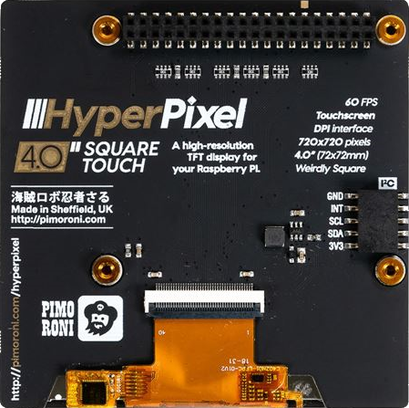
Most of my photos were in a 9:16 ratio that I cropped to 1:1 and I didn't want there to be an awkward border on the sides of the photos. To preserve the square shape, I bought the "Oddly Square" screen from Pimoroni.
Power Button
Yellow is one of those colors that I have come to love. A Google search will tell you that the colors commonly symbolize joy and happiness. A sense of warmth and brightness. Not to go Bob Ross on you, but I think its value and symbolism is best juxtaposed' against the dark, much like in life. I wanted to add a touch of personal style to the project by making the power button display a nice yellow ring. I bought an RGB push-button, and used resistors based on the current of my circuit to control the color. Raspberry Pis have what are called General-Purpose Input/Output(GPIO) Pins. The different pins have different functions, but I was able to use two of them to jump power to the Pi, and act as an "On" switch. Once powered on, I made a script that continuously read the state of the button, so that if it was pressed while in an on state, it would also be able to send a shutdown signal, turning the Pi off.
Assembly
It's been some time now, but I remember this being a lot more difficult, and taking more time than it should have on paper. Once again, probably due to my novice skills/resources. I was using a Weller soldering iron to solder my wires. Not really intended for what I was doing! Compared to the freakin' Pinecil I picked up this year(not sponsored but Pine64 can sponser me if they want). Amazing. Amazing little iron. I digress.
I glued the Raspberry Pi to the back corner of the container, so that the ports for power, audio, etc., would stick out of the openings I made for them. I then glued the amplifier/control so that the volume control knob stuck out the front. Because I wanted power to be plugged into the back, I bought a GPIO extender cable for the Pimoroni screen. After a bit of research, I found out that certain pins did not need to be used by the screen, freeing up a few for me to allocate one of them to the power on/off push-button. I made this connection after threading the push-button in place. Much of the wiring had to be worked on while the Pi was pulled through the screen opening, adding difficulty.
I unsoldered the speaker connections and pulled the wires through the front of the box. This made it easier to resolder them, and pull everything back inside so that the rounded back of the speaker blocks could be inserted, and screwed down to the front of the box. Once these other components were in place, I connected the screen to the GPIO extension cable to see the project working when powered on.
Admittedly, I worked on this project as a gift. Time was running out, and I still needed to fit the screen in place. The hole I cut should have had perfect clearance for fitting the square screen, but when I worked to get it in place, I cracked it. The next power on of the Pi displayed broken LCD crystals and lines throughout the display. My heart sunk!. I guess on the bright side, it had to be turned on to see it.


